How to Test a Surge Protector With a Digital Multimeter?

Time:2026-09-11 Author:Aria
0%

Testing a surge protector sounds simple, but the procedure demands careful judgment. This guide explains how to test a surge protection device with a digital multimeter safely and realistically. A multimeter can reveal open circuits, damaged connections, or abnormal resistance. It cannot prove that the device will stop a powerful transient.

Mike Holt, a respected electrical educator, often states, “Safety is not an option.” That principle matters here. Disconnect the protector from the outlet before touching its terminals. Remove connected equipment, inspect the casing, and look for cracks, burn marks, melted plastic, or a triggered status window. Work on a dry, nonconductive surface. Keep one hand away from energized parts.

Set the meter correctly before measuring. Continuity mode may show whether an internal path remains, while resistance mode can reveal a shorted component. However, readings vary between models. Metal-oxide varistors, thermal disconnects, indicator circuits, and filters can produce confusing results. A near-zero reading may indicate failure, but an open reading does not always confirm protection. The protector may have sacrificed its clamping ability without leaving an obvious meter signature.

That limitation is important. I have seen ordinary-looking units fail after a storm. A green light can also create false confidence. It may only confirm power or indicator continuity. The most reliable assessment combines visual inspection, manufacturer instructions, documented test limits, and replacement history. If the enclosure is damaged, the cord is hot, or the reading seems inconsistent, stop testing. Replace the device or ask a qualified electrician for evaluation. A multimeter is useful, but it is not a complete surge laboratory.
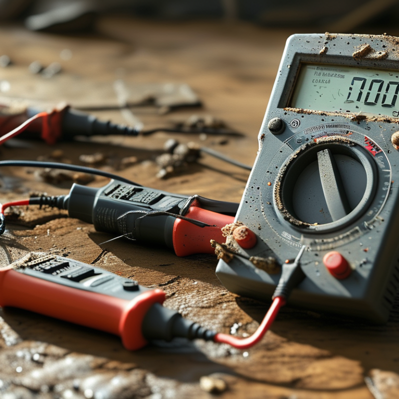
How to Test a Surge Protector With a Digital Multimeter?

Understand Surge Protector Components and Safety Precautions

How to Test a Surge Protector With a Digital Multimeter?

Before testing, unplug the surge protector from the wall and remove every connected device. Let it rest for several minutes. Surge protectors commonly contain metal-oxide varistors, thermal fuses, indicator circuits, and noise filters. These parts work together, but a digital multimeter cannot confirm complete surge protection. It mainly reveals obvious faults.

Set the meter to resistance or continuity mode. Check the plug pins and output contacts only when the unit is fully disconnected. A steady low-resistance reading between line and neutral may indicate a short circuit. A normal protector often shows very high resistance, although the reading can change briefly while internal components charge. Test each outlet carefully, and inspect the casing, cord, and grounding pin. Burn marks, cracks, melted plastic, loose contacts, or a failed indicator justify replacement. Do not open the housing. The internal thermal fuse or varistor may still hold dangerous energy. Never test a live outlet in resistance mode.

Tips: Use insulated probes and dry hands. Keep the protector on a nonconductive surface. Record unstable readings instead of guessing. A normal meter result does not prove the device is safe during a major surge. I would replace an old or overheated unit, even when its resistance appears normal. This is the part many quick tests miss. When uncertainty remains, ask a qualified electrician to inspect it.

Prepare the Digital Multimeter and Surge Protector for Testing

How to Test a Surge Protector With a Digital Multimeter?

Prepare the Digital Multimeter and Surge Protector for Testing

Begin with a completely de-energized setup. Unplug the surge protector from the wall outlet. Disconnect every appliance and allow the unit to rest for several minutes. Stored energy can remain inside some components. Wear safety glasses and work on a dry, nonconductive surface.

Inspect the plug, cable, housing, switch, and indicator light carefully. Look for melted plastic, dark marks, cracked insulation, or a burning smell. NFPA’s Home Fires Involving Electrical Distribution and Lighting Equipment report recorded about 31,330 such fires annually from 2015 to 2019. That figure reinforces a simple point: physical damage deserves more attention than one meter reading.

Set the digital multimeter to resistance or continuity mode. Confirm that its leads work on a known resistor before testing. Do not measure resistance on a connected or energized protector. A healthy metal-oxide varistor may show very high resistance at the meter’s low test voltage. Therefore, an open reading does not prove reliable surge protection. That assumption is easy to make, yet incomplete.

For three-prong models, check the ground path only when accessible without opening the enclosure. Never defeat the grounding pin. IEC 61643-11 treats surge protective devices as components requiring performance testing beyond ordinary household multimeter checks. A meter can reveal a short circuit or broken connection, but it cannot verify clamping voltage. I would not declare a protector safe from one number.

How to Test a Surge Protector With a Digital Multimeter?

Prepare the Digital Multimeter and Surge Protector for Testing

Before testing resistance or continuity, unplug the surge protector and disconnect all connected equipment. Set the multimeter to the correct function and range. For a nominal 120 V AC system, line-to-neutral and line-to-ground measurements are typically close to 120 V, while neutral-to-ground should be close to 0 V. Never use resistance or continuity mode on an energized circuit.

Test Continuity and Resistance Across the Protection Circuit

How to Test a Surge Protector With a Digital Multimeter?

Unplug the surge protector from the wall before testing. Wait several minutes, then press its power switch to help remove stored charge. Never measure resistance on an energized circuit. Set the digital multimeter to continuity or the lowest resistance range. Test the plug, switch, and outlet path only when the protector is disconnected. A working power path may show very low resistance, while a broken thermal fuse or switch may show OL, meaning open circuit.

For the protection circuit, resistance is usually more informative than a beep. Measure across each accessible surge-suppression component, such as the line-to-neutral or line-to-ground path. A healthy component commonly shows very high resistance or OL during a low-voltage meter test.

A near-zero reading suggests a shorted component and indicates that the protector should not be used. However, a normal reading does not prove full surge protection. A meter cannot verify clamping voltage or energy capacity. Internal construction also varies, so forcing probes into sealed parts can create a dangerous mistake.

Tips: Use insulated probes and keep your fingers behind the guards. Record the readings before repeating the test. If values change sharply, stop and replace the unit through a qualified service channel. I once expected continuity through every section, but that assumption was wrong; protective parts often block direct current. Check the circuit design before judging the result.

Measure Voltage and Check for Abnormal Readings

Testing a surge protector with a digital multimeter starts with a safe voltage check. Unplug sensitive equipment and inspect the strip for cracks, heat marks, loose sockets, or a damaged cord. Set the meter to AC voltage, not resistance or continuity. Plug the surge protector into a known-good wall outlet. Place one probe in the protector’s line slot and the other in neutral. The reading should closely match the outlet’s normal voltage.

Compare it carefully.

Next, measure the wall outlet directly, using the same meter and range. A large difference may indicate a faulty switch, loose connection, or damaged internal wiring. You can also check line-to-ground and neutral-to-ground voltage if the outlet is properly grounded.

Avoid forcing probes into narrow openings. Keep your fingers behind the probe guards. Never open the protector while it is connected to power.

An abnormal reading deserves caution. Zero voltage may point to a failed cord, switch, or internal fuse. A fluctuating reading can suggest a poor connection, but a low battery or loose probe can create similar symptoms. Check the meter on a known source before judging the protector. A normal voltage reading does not prove that the surge components still work. Many protective parts can degrade without changing ordinary AC voltage. I sometimes find this limitation easy to overlook. A multimeter confirms basic electrical continuity and voltage, not complete surge protection performance. Replace the unit if it shows burning, unusual heat, repeated tripping, or physical damage.

Interpret Test Results and Decide Whether Replacement Is Needed

Unplug the surge protector before testing it. Wait several minutes for internal capacitors to discharge. Inspect the case, cord, plug, and status light. Cracks, melted plastic, scorch marks, or a burnt smell require replacement immediately. Power off first.

Set the digital multimeter to resistance or continuity mode. Test the grounding path from the ground pin to each ground contact. A stable, low-resistance reading usually indicates continuity. An open reading suggests a damaged conductor. Test line and neutral separately, but remember that metal-oxide varistors may show very high resistance. The meter may display OL. That is normal in many designs. A low, steady resistance is suspicious. My first mistake was treating OL as proof of protection. It is not.

A multimeter cannot measure clamping voltage, response time, or remaining surge capacity. It also cannot confirm whether an aging varistor will respond correctly. NEMA application guidance explains that an indicator usually shows disconnect status, not complete protective performance. Replace the unit when protection status disappears, damage appears, or a major surge event occurred. NFPA analysis of 2015–2019 data recorded an annual average of about 32,600 home fires involving electrical distribution and lighting equipment. That statistic does not prove the protector failed, but it supports cautious replacement decisions. If the readings seem inconsistent, stop testing and use a qualified electrician. The low-cost test may hide a high-risk fault.

FAQS

: How should I prepare a surge protector for testing?

: Unplug it from the wall. Wait several minutes. Press the power switch to discharge stored energy.

Which multimeter setting should I use?

Select continuity mode or the lowest resistance range. Never test resistance on an energized circuit.

What does low resistance usually indicate?

A stable, low reading may indicate a continuous plug, switch, or grounding path. Check the circuit design first.

What does “OL” mean on the display?

“OL” usually means an open circuit. It may be normal across protection components that block direct current.

Is a near-zero reading across a protection component safe?

No. A near-zero reading may indicate a shorted component. Stop using the protector and replace it.

Can a multimeter confirm complete surge protection?

No. It cannot measure clamping voltage, response time, or remaining energy capacity. The test has limits.

What physical signs require immediate replacement?

Replace the unit after cracks, melted plastic, scorch marks, or a burnt smell appear. Power off first.

What should I do if readings change sharply?

Stop testing. Record the readings and seek qualified service. I once expected continuity everywhere, but that was wrong.

Does a missing status light prove the whole protector failed?

It suggests a protection-status problem, but it cannot explain every internal fault. Replacement is the safer choice.

When should I avoid testing the unit myself?

Avoid forcing probes into sealed parts or testing inconsistent circuits. A cheap test can hide a serious fault.

Conclusion

This guide explains how to test a surge protector safely with a digital multimeter, including how to test a surge protection device with a digital multimeter without relying on a simple visual inspection. It begins by identifying the main protection components, such as surge-limiting elements, switches, outlets, and indicator circuits, while emphasizing essential precautions: disconnect the device from power, remove all connected equipment, and allow sufficient time for stored energy to dissipate.

The testing process includes preparing the multimeter with the correct mode and range, checking continuity and resistance across the protection circuit, and measuring voltage only when it is safe and necessary. Abnormal readings, infinite resistance, unexpected continuity, overheating, damaged insulation, or a failed indicator may suggest that the protector is no longer reliable. Because a multimeter cannot confirm every aspect of surge protection performance, any device showing physical damage, unstable results, or unclear test readings should be replaced rather than reused.

Aria

Aria

Aria is a dedicated marketing professional with a deep passion for innovative strategies and a keen understanding of our company's product offerings. With a wealth of experience in the industry, Aria excels at crafting engaging content that highlights the unique features and benefits of our......