Ensuring the safety, surge mitigation, and structural integrity of global Power Factor Correction (PFC) banks and solar installations.


In modern commercial and industrial electrical distribution grids, efficiency is measured not only by active energy consumption but by the structural performance of the power distribution infrastructure. Linear and non-linear inductive loads—such as induction motors, heavy machinery, high-intensity discharge (HID) lighting systems, and switch-mode power supplies—require both active (kW) and reactive power (kVAR) to function. While active power performs the actual mechanical work, reactive power is essential to generate magnetic fields.
The vector ratio of active power to apparent power (kVA) is designated as the Power Factor (PF). A lower power factor indicates an inefficient system that draws excessive, non-productive currents from the electrical utility grid. This inefficient circulation of current results in increased thermal degradation across electrical conductors, excessive voltage drops, and severe financial penalties imposed by utility operators.
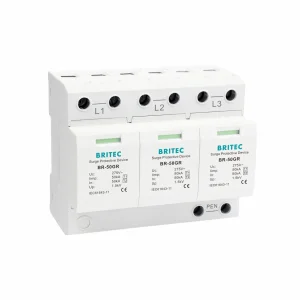
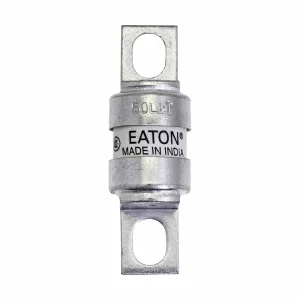
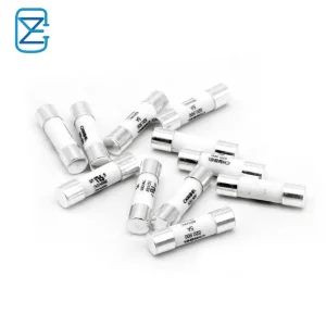
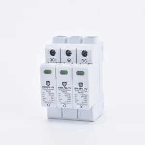
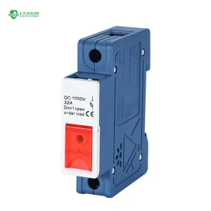
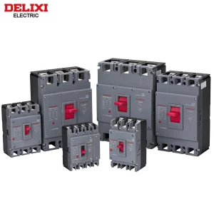
Power Factor Correction (PFC) systems, primarily constituted of automated capacitor banks or advanced electronic compensation loops, resolve this by acting as local reactive current sources. By relieving the distribution grid from transmitting reactive power, PFC units optimize system load capabilities, reduce active power losses, and enhance overall system capacity. Wenzhou Phlox Energy, with its deep foundation in high-voltage circuit protection, provides the critical component architectures—including DC MCBs, surge protection devices, and specialized high-capacity PV fuses—that secure PFC systems against transient faults and overheating.
The true work-producing electrical energy that drives motors, lighting, and computing architectures. This is the billable component directly linked to operational throughput.
The magnetizing vector necessary to sustain inductive fields. It oscillates between source and load without being consumed, creating additional grid burden.
The vector summation of active and reactive components. Transformer capacity, cabling thickness, and grid infrastructure are dimensioned based on this figure.
Modern utility operators enforce strict grid regulations globally to prevent voltage fluctuations and transmission losses. Power systems facing low power factors risk severe penalty tariffs. To satisfy these rigorous grid codes, industrial plants utilize three distinct structural methods of Power Factor Correction:
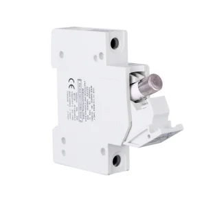
Installed at the main low-voltage incoming switchboard of a facility, centralized PFC systems use programmable logic controllers (PLCs) and microcontrollers to monitor load fluctuations. They dynamically switch step-controlled capacitor steps in or out of the circuit via heavy-duty magnetic contactors or solid-state thyristors. This centralized setup guarantees broad system compliance with localized grid codes but requires robust overcurrent and short-circuit protection, as the total energy capacity of the busbars is extremely high.
This method groups multiple inductive loads functioning under similar patterns—such as a series of ventilation fans or conveyor belts—and connects a fixed capacitor bank to their shared distribution panel. Group compensation relieves downstream cabling of reactive currents, reducing localized I²R heat losses within the distribution networks.
By connecting a dedicated capacitor directly to the terminals of a large induction motor, individual correction ensures reactive current flows only between the motor and the capacitor. This eliminates reactive power from the entire upstream wiring architecture. However, it requires highly reliable fuses and surge protectors to prevent localized transient failures from causing cascading plant outages.
The global push toward carbon neutrality, combined with rising electricity costs, has accelerated the adoption of power quality solutions worldwide. Industrialized nations in Europe and North America have updated their grid codes to enforce stricter power factor ranges (often requiring 0.95 or higher). In rapidly expanding manufacturing hubs across Asia, high load density makes grid stability a matter of national energy security.
Additionally, the rise of variable renewable energy sources like wind and solar PV introduces high levels of instability and harmonic distortions. Modern photovoltaic systems require dynamic reactive power control at the utility level to balance active power generation. Consequently, the boundary between solar energy distribution and power factor correction is merging. Large solar farms utilize smart inverters and Static Var Generators (SVGs) to actively inject or absorb reactive power, ensuring grid compatibility.
Power quality requirements depend heavily on regional environmental and infrastructural conditions:
Wenzhou Phlox Energy Co., Ltd. is a leading professional manufacturer and supplier specializing in solar photovoltaic protection and electrical connection solutions. With more than 10 years of intensive industry experience, we are dedicated to the research, development, production, and innovation of high-quality solar accessories and low-voltage electrical products for global renewable energy markets.
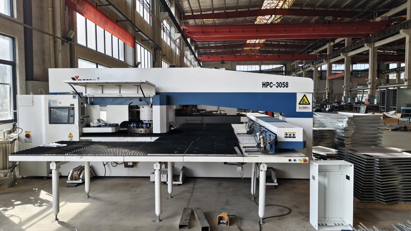
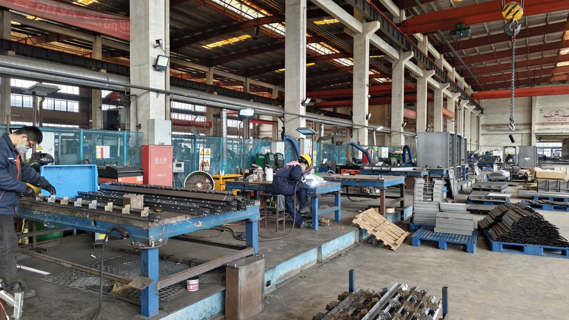
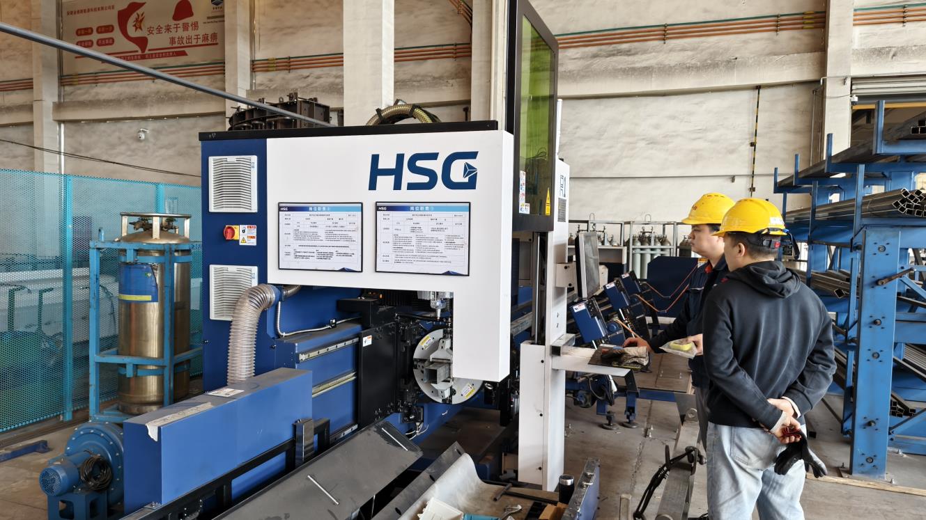
Our manufacturing facility covers an area of over 11,500 square meters and is equipped with 7 advanced production lines, more than 100 automated production machines, and a skilled workforce of over 150 employees. With strong production capacity and efficient management systems, our annual output value exceeds USD 20 million.
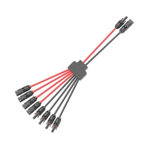
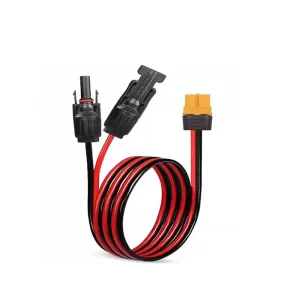
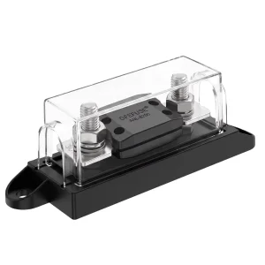
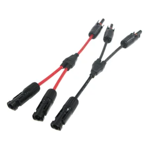
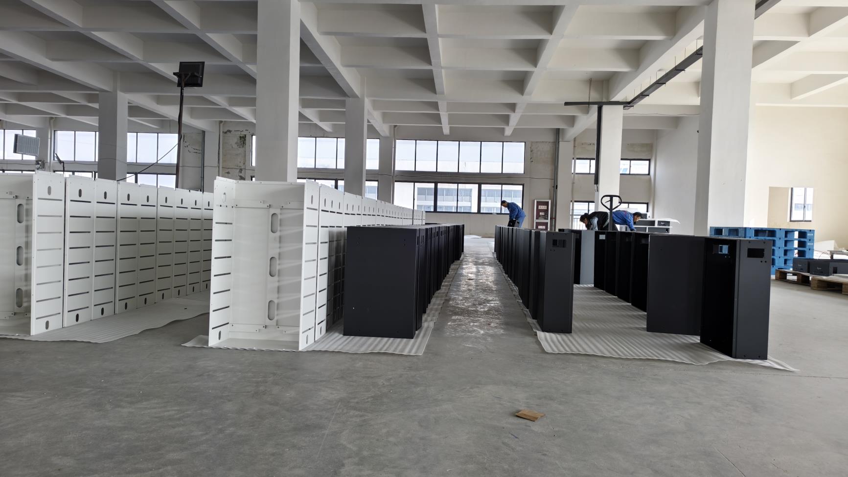
Phlox Energy specializes in the production of DC miniature circuit breakers (MCBs), surge protective devices (SPDs), photovoltaic fuses, solar connectors, DC isolator switches, distribution boxes, combiner boxes, and other solar power system components. Our products are widely used in residential, commercial, and industrial photovoltaic installations around the world.
Quality is at the core of everything we do. Our products are manufactured in strict accordance with international standards and have obtained certifications including CE, TUV, IEC, CB, and ISO 9001. Every product undergoes comprehensive quality inspections and rigorous testing procedures to ensure safety, reliability, and long-term performance in demanding environments.
Driven by continuous innovation, our experienced R&D team works closely with customers to develop customized solutions that meet evolving market requirements. We also provide OEM and ODM services, helping partners build competitive product portfolios and strengthen their market presence.
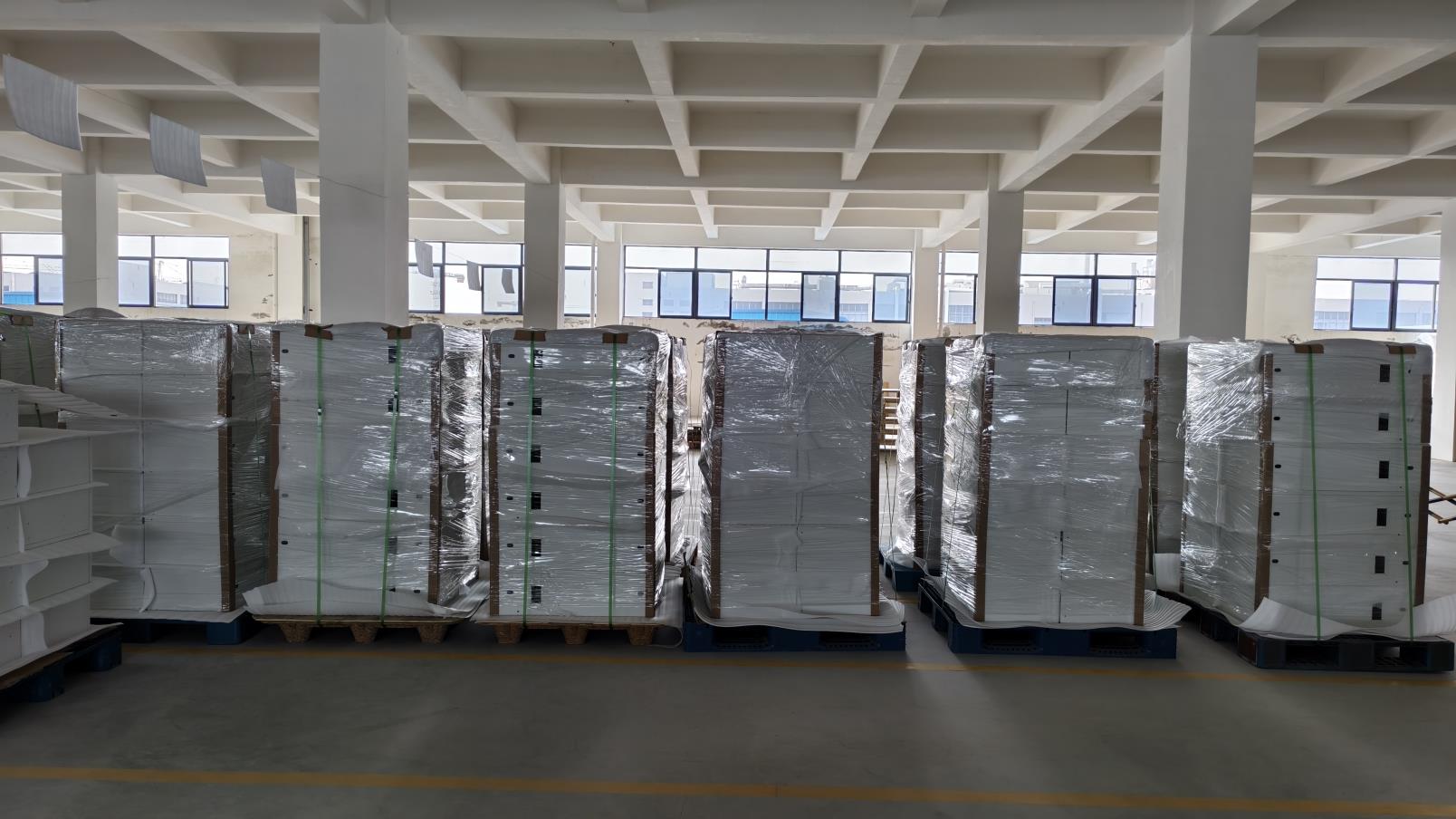
Having successfully participated in more than 3,900 solar energy projects worldwide, Phlox Energy has earned a strong reputation for premium product quality, competitive pricing, reliable delivery, and professional after-sales support. Our commitment to customer satisfaction and long-term cooperation has made us a trusted partner for distributors, installers, EPC contractors, and solar energy companies across the globe.
Precision manufacturing and automated assembly processes ensure maximum durability and safety for all electrical components.


The field of power factor correction is undergoing a paradigm shift, transitioning from passive electrical arrays to highly adaptive, digitized power management systems.
Traditional capacitor banks operate in discrete steps, meaning they can sometimes over-compensate or under-compensate depending on the load. In contrast, SVGs utilize fast-switching Insulated Gate Bipolar Transistors (IGBTs) to inject reactive current in real time, matching the system's exact requirements down to the microsecond. This dynamic compensation is crucial for modern industrial environments containing high concentrations of sensitive electronics.
Non-linear loads generate harmonic currents that distort the voltage waveform. Standard capacitors act as low-impedance paths for these high frequencies, which can cause resonance, overheating, and premature failure. To prevent this, modern systems integrate detuned reactors—large inductors connected in series with the capacitors—or Active Harmonic Filters (AHFs) that actively cancel harmonic currents.
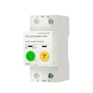
By integrating IoT sensors and edge computing into distribution panels, operators can monitor power factor, voltage spikes, and harmonic distortion in real time. Machine learning algorithms analyze these data streams to predict when a capacitor's dielectric properties are starting to degrade, allowing for proactive maintenance before a critical failure occurs.
Global operations require strict adherence to international safety standards. Phlox Energy manufactures all protection equipment to meet or exceed:
Complete your power distribution, solar PV, and control architectures with our field-tested components.